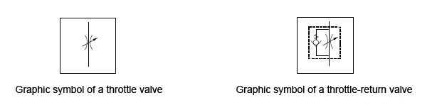
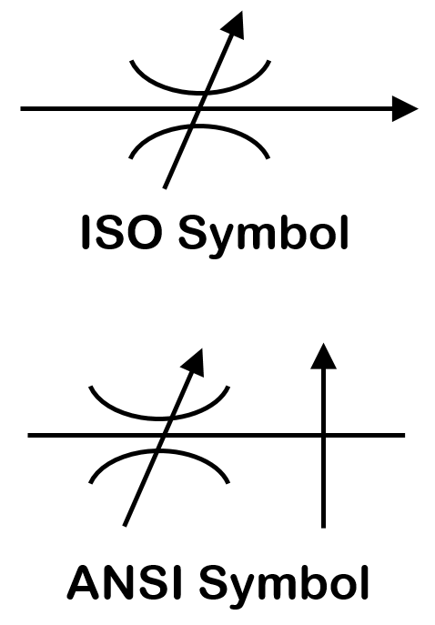
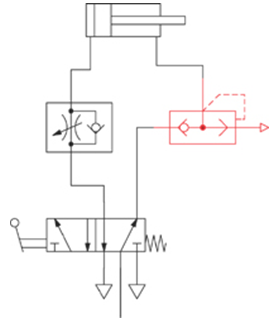
Pneumatic Speed Control Valve Symbol

Reading Fluids Circuit Diagrams Hydraulic Pneumatic Symbols

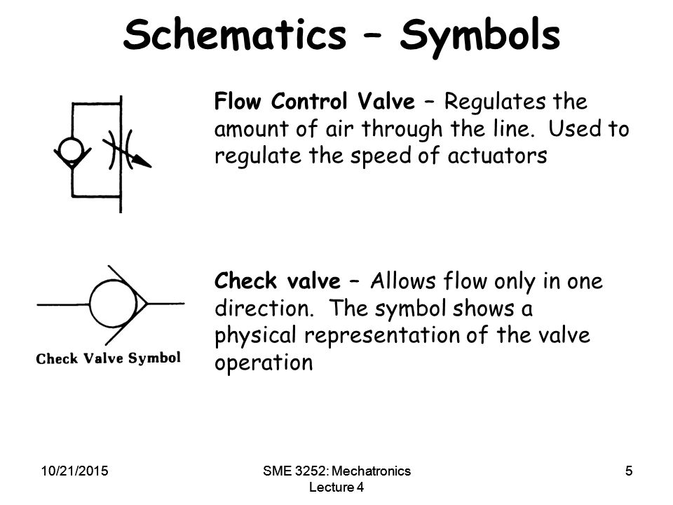
Tip 14 Go With The Flow Control Hydraulics Pneumatics
Pneumatic Circuit Symbols Explained Library Automationdirect
Pneumatic And Hydraulic Actuation System Cont Ppt Video Online Download

Untangling Pneumatic Circuit Symbols Hydraulics Pneumatics
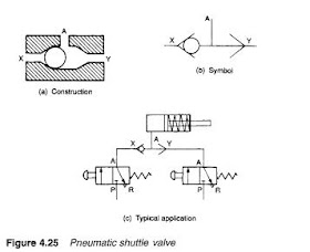
Valves Which Control The Direction Of The Flow Of The Compressed Air Spool Valves
Pneumatic symbols only when the design fails does it draw attention to itself.
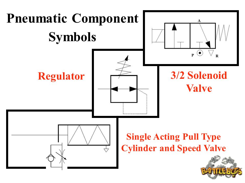
Pneumatic speed control valve symbol. Pneumatic circuit symbols explained. Mount these valves directly to cylinder ports eliminating additional tubing between the cylinder and valve for better control than inline valves. Hydraulic and pneumatic picture symbols for fluid power schematics define their function in engineering drawings diagrams or plans. Reference for pictures symbols.
In the hydraulic valve fluid is returned to the tank from port t. A close study of most air logic control circuits will reveal that there are only six basic valve functions commonly used. As the phrase fluid power implies these symbols cover both hydraulic and pneumatic components. In the pneumatic valve return air is vented from port r.
Speed controller meter out speed cotroller in line. Made of plastic and stainless steel parts they have excellent corrosion resistance. When it succeeds it s invisible. Schematic symbols and circuit design help.
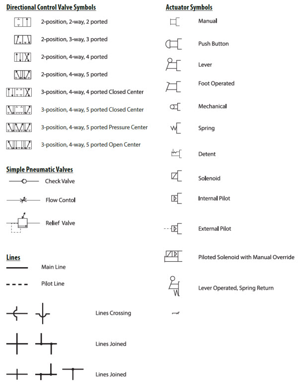
They are commonly represented with symbols. These symbols needs to be understood before you can correctly interpret pneumatic drawings and diagrams. Any exceptions are noted. These details may include the size function pressure rating and connection type of the valve.
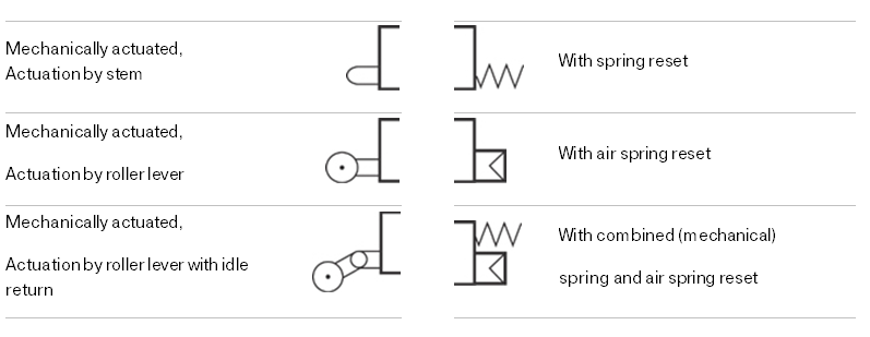
These six basic valve symbols when combined with the basic actuator symbols comprise virtually all the directional valve symbols needed for air logic control. Directional air control valves are the building blocks of pneumatic control. Symbols show the methods of actuation the number of positions the flow paths and the number of ports. Pneumatic circuit symbols representing these valves provide detailed information about the valve they represent.
An engineer may also include specific details below the control valve symbol. They control the speed of air powered equipment by adjusting the volume of airflow. 3 2 mechanical valve with integrated exhaust port basic. Most control valves however have four ports shown in hydraulic and pneumatic forms in figure 4 1.
Mechanical and air operated valves. Pneumatic systems are still popular in older plants and even in modern plants where their use is inevitable. The symbols for these valve functions are shown in left graphic. Read more about hydraulic symbology in a series from author josh cosford.
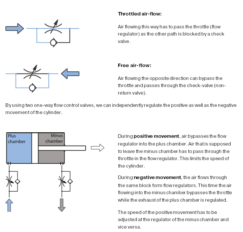
Unidirectional flow control valves are used to limit the speed of the cylinder s operation by controlling the flow direction of compressed air. Heat exchangers filters lubricators and dryers hydraulic pumps relief and unloading valves continued directional control valves continued. In both the load is connected to ports labeled a b and the pressure supply from pump or compressor to port p.
The Pneumatic Cylinder Part 2

Pneumatics Symbols Din Iso1219 1 03 96 Graphic Symbols For Pneumatic Equipment Volume Symbol Description Alexander Ospina Academia Edu
Iso Schemes Of Directional Control Valves

Pneumatic Symbols Pneumatics Guides Rowse Pneumatics

Pneumatic Misc

Hydraulic Valve Symbols Google Search Studying Math Hydraulic Mechatronics
Using Graphic Symbols To Illustrate Basic Circuit Designs Ppt Video Online Download
Engineering Types Of Control Valves Part 2

Application Notes Speed Control Actuator Synchronisation Hydraulics And Pneumatics

5 2 4 2 Way Pneumatic Valve How They Work Tameson
How Does A Pressure Compensated Flow Control Valve Work Engineering360
Grouping And Construction Of Control Valves

Hydraulic Restriction Check Valves Hydraulic Valve

