Pneumatic Actuation System Layout

Hydraulic Symbols Pneumatic Symbol Library Schematic Design Hydraulic Systems Engineering Symbols
Simplified Pneumatic Actuator Design And Operation Engineers Edge Www Engineersedge Com

How To Read Pneumatic Circuit Diagram Circuit And With Images Circuit Diagram Circuit Hydraulic Systems

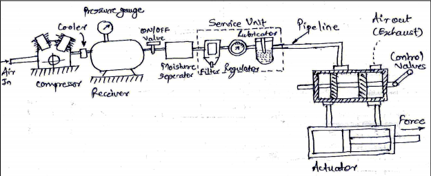
Draw General Layout Of Pneumatic System And State Function Of Each Component In It
Chapter 5 Pneumatic And Hydraulic Systems Hydraulics Pneumatics

General Layout Hydraulic Pneumatic System

In general pneumatic systems are used for gripping and or moving operations in various industries.
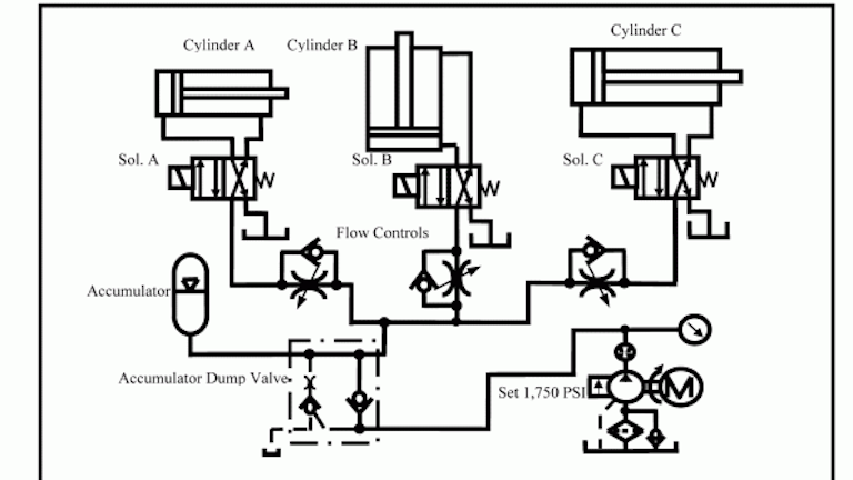
Pneumatic actuation system layout. Piston type fluid accumulator general design. Pneumatic actuators come in many designs and sizes and include a variety of mounting methods internal features and options to provide a robust solution in industrial environments table 2. For instance there are thousands of types sizes and variations of cylinders and valves from off the shelf versions to custom designs. However when a large amount of force is required to operate a valve for example the main steam system valves hydraulic actuators are normally used.
Quarter turn rotary actuators. It operates by a combination of force created by air and spring force. Diaphragm cylinders rodless cylinders telescoping cylinders through rod cylinders etc. In order to get a better overview we position the air preparation on the bottom and the actuators on the top of the drawing.
There are many styles of pneumatic actuators. A simplified pneumatic actuator diagram of a pneumatic actuator is shown in figure f1. A rubber diaphragm separates the actuator housing into two air chambers. Understanding pneumatics is a matter of physics.
It s reliable economical and surprisingly easy to use. Actuators are output devices which convert energy from compressed air into the required type of action or motion. The sketch exemplifies a pneumatic system at the machine level. It operates by a combination of force created by air and spring force.
A simplified diagram of a pneumatic actuator is shown in figure 1. They are ideal for quick opening and closing in both on off and control applications. Pneumatic actuator design and operation. Hydraulic actuator design and operation pneumatic actuators are normally used to control processes requiring quick and accurate response as they do not require a large amount of motive force.
Pneumatic actuation plays a major role in today s world of computerized automation. They display the route of the compressed air. Pneumatic system design considerations. Pneumatic systems as a whole can be simple but this simplicity can be deceptive when it comes to selecting components.
The actuator positions a control valve by transmitting its motion through the stem. Pneumatic actuators are the most commonly used valve automation systems. Air cylinders and motors are the actuators which are used to obtain the required movements of mechanical elements of pneumatic system. A safe pneumatic system design starts at the connection to a machine s air preparation hardware and continues to correctly pairing valves with cylinders.
Image Result For Log Splitter Design Plans Log Splitter Wood Splitter Splitters

Plumbing System Controls Valves Valve Plumbing Valves Plumbing
Draw A General Layout Of Pneumatic System And State The Function Of Components Topicwise Paper Solutions For Msbte

Nordyne Air Handler Wiring Diagram Fan Circuit Free For Ac Model E2eb 015ha 2 With E2eb 015ha Wiring Diagram Carrier Furnace Electric Furnace Thermostat Wiring

Small Below Grade Ground Run With Installing Basement Toilet Plumbing Diagrams For Closet And Bathroom

Plumbing Diagram For Pool System Curve In Pool Pump System Plumbing Diagrams On Head And Flow Pool Pump System Plumbing Diagrams

Branch Vent A Vent Connecting One Or More Individual Vents To A Stack Vent Building Systems Study Time Vented

This Model Uses Scenes Do Not Download Into Another Model Open As A New File This Sliding Blast Gate Is Pneu Dust Collection Mechanical Projects Duct Work

For Pneumatic Control System Components Choose Dasservicesinc A Broad Range Of Pneumatic Tools Like Vacuu In 2020 Rose Crafts Diy Aquarium Aquarium Fish Tank

Pin By Carlos Senosiain On That S A Fact In 2020 Blacksmith Power Hammer Power Hammer Power Hammer Plans

Engine Diagram On Peugeot 8 V8 Di 2020

Palma Air Defense Missile Gun And Gun System Kaskus The Largest Indonesian Community Weapon Guns Weapons Aircraft

Single Acting Pneumatic Actuator Manufacturer Suppliers In The Globe In 2020 Control Valves Actuator Chemical Industry

